Product Description
Product Description
|
Item |
China Manufacturers High Precision Nylon Steel Stainless Plastic Casting Double Spur Gear |
|
Material |
ABS, PC/ABS, PP, PC, POM(Delrin), Nylon 6, Nylon 6/6, PA 12, HDPE, LDPE, PS(HIPS), SAN/AS, ASA, PVC, UPVC, TPE, TPR, PU, TPU, PET, PEI(Ultem), PSU, PPSU, PPE/PS, PTFE, GPPS, PPO, PES, CA, etc |
|
Certificate |
IATF 16949:2016 / ISO 9001:2015 / ISO 45001:2018 / ISO 14001:2015 /REACH/ROHS/MSDS/LFGB/F D A |
|
Drawing Format |
.stp / .step / .igs /.CHINAMFG /.dwg / .pdf |
|
Color |
Almost all PMS colors available. |
|
Parameters |
Inch, centimeter, millimeter, etc. |
|
Function |
Industrial parts /daily supply / Medical grade supply, etc. |
|
Surface Treatment |
Matte, Common polishing, Mirror polishing, Texture, Plating, Power Coating (Painting), Laser Engraving, Brushing, Marbling, Printing etc. |
|
Mold Material |
S136H, 718H, NAK80, P20, H13, etc. |
|
Mold Precision |
If no special request, apply to SJ/T10628-1995 standards, class 3. |
|
Mold Life-cycle |
100,000-500,000 shots. |
|
Packing |
Pack in bulk / poly bag / bubble bag / color box. |
|
Sample |
Available. One cavity sample mold or 3D printing. |
|
Price Tip |
The price shown above is just for reference, final actual price depends on your design, material request, surface treatment, order qty, package request, etc. |
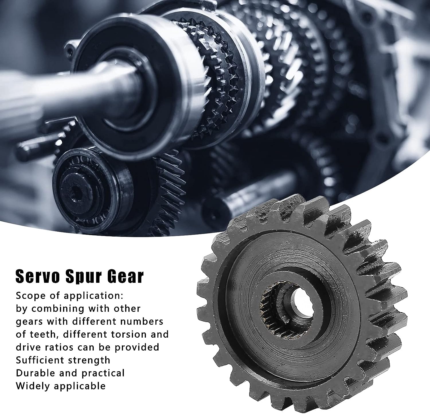
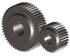
Differential Custom Internal Nylon Plastic Double Spur Gear
1. Rapid Prototyping & On-demand production services;
2. Professional DFM Report before Mould Making;
3.Capability for Plastic Injection Molding is up to 1500mm
DFM Report (Design for Manufacturability) for Reference.
Some Custom CHINAMFG & Moulds for Your Reference.
Neway Highly Welcome Your Own Custom Designs !!!
Neway Support Custom Design Moulds & Moulds Export.
Neway Can Also Provide Mould Spare Parts Export, eg: Slider, Inserts, Ejector Pins, etc.
NEWAY has complete production chain from R&D, Rapid Prototypes, mould design, mould making, components production, assembling, packing to export. Having 1 supplier like CHINAMFG for the complete assembly will allow for better design, quality, and fit of all the individual parts.
The most common used surface treatment are: Matte, Texture (fine texture, rough texture…), Common Polishing, Mirror Polishing, Laser Engraving, Printing, Plating, Brushing, Marbling), etc. You can view below surface pictures for reference
Company Profile
Our Advantages
Good reviews of customer
Certifications
Below are some inspection equipment for reference:
And attach the injection molding CHINAMFG inspection report for reference:
Packaging & Shipping
FAQ
Q1. How soon can I get a precise quotation for custom plastic injection part?
A1: Please send us your inquiry by email or Alibaba TM message. Once we confirm the design (Feature details with parameters), material, color, qty, we can provide quotation within 24 HOURS.
Q2: Can I get a free sample, how long will it take?
A2: a. For standard products we have in stock, YES for free sample, but the express fee will be charged in advance.
Mostly, it takes 3-10 days.
b. For custom products, sample fee is determined by the detailed sample requirements. Normally, it takes 7-15 days.
Q3: Can you make custom parts based on my sample?
A3: Yes, you can send the sample to us by express and we will evaluate the sample, scan the features and draft 3D drawing for production.
Q4: What does your OEM service include?
A4: We follow up your request from the design idea to the mass production.
a. You can provide 3D drawing to us, then our engineers and production teams evaluate the design and quote you the precise cost.
b. If you don’t have 3D drawing, you can provide 2D drawing or draft with features details with full dimensions, we can draft 3D drawing for you with fair charge.
c. You can also customize Logo on the product surface, package, color box or carton.
d. We also provide assembly service for the OEM parts.
Q5. What is your payment term?
A5: We accept T/T, Paypal, Western Union, L/C, Alibaba Trade Assurance.
Work with Neway, your business is in safe and your money is in safe!
If you can dream it, we can build it!
| Application: | Motor, Electric Cars, Motorcycle, Machinery, Car, Others |
|---|---|
| Hardness: | Hardened Tooth Surface |
| Gear Position: | Internal Gear |
| Manufacturing Method: | Plastic Injection |
| Toothed Portion Shape: | Bevel Wheel |
| Material: | Plastic |
| Samples: |
US$ 10/Piece
1 Piece(Min.Order) | |
|---|
| Customization: |
Available
| Customized Request |
|---|

How do you address noise and vibration issues in a spur gear system?
Noise and vibration issues in a spur gear system can significantly impact its performance, efficiency, and overall user experience. Here’s a detailed explanation of how to address noise and vibration issues in a spur gear system:
- Gear Design: Optimize the gear design to minimize noise and vibration. Consider factors such as tooth profile, gear module or pitch, and the number of teeth to ensure smooth and quiet gear operation. Proper gear design helps reduce gear meshing impacts and tooth-to-tooth variations, which are common sources of noise and vibration.
- Accurate Gear Alignment: Ensure precise gear alignment to minimize misalignment-induced noise and vibration. Misalignment between the gears can cause uneven loading, increased backlash, and gear meshing irregularities, leading to noise and vibration. Proper alignment techniques, such as using alignment tools or measuring devices, should be employed during gear installation and maintenance.
- Surface Finish and Tooth Quality: Ensure proper surface finish and high-quality tooth profiles on the gears. Rough surfaces or manufacturing defects can contribute to noise and vibration. Gears with accurate tooth profiles and smooth finishes experience better meshing and reduced friction, resulting in lower noise and vibration levels.
- Lubrication: Proper lubrication is crucial for reducing friction, wear, and noise generation in spur gear systems. Use the recommended lubricant type and ensure sufficient lubricant film thickness between gear teeth. Regular lubricant analysis and replacement are important to maintain optimal lubrication performance and minimize noise and vibration issues.
- Load Distribution: Evaluate the load distribution within the gear system to minimize localized loading and potential noise sources. Proper gear design, tooth profile optimization, and gear arrangement can help distribute the load evenly, reducing noise and vibration caused by uneven loading conditions.
- Resonance Analysis and Damping: Conduct resonance analysis to identify and address potential resonant frequencies within the gear system. Resonance can amplify noise and vibration. Techniques such as adding damping materials, using vibration isolators, or adjusting gear configurations can help mitigate resonance-related noise and vibration issues.
- Noise and Vibration Testing: Perform noise and vibration testing during the development and maintenance stages of the gear system. This involves using specialized equipment to measure and analyze noise and vibration levels. Testing helps identify specific sources of noise and vibration, allowing for targeted solutions and improvements.
- Isolation and Absorption: Implement isolation and absorption techniques to minimize noise and vibration transmission to surrounding structures or components. This can include using vibration isolators, resilient mounts, or incorporating vibration-absorbing materials to reduce the propagation of noise and vibration beyond the gear system.
- Regular Maintenance and Inspection: Implement a proactive maintenance program to monitor gear performance and identify potential noise and vibration issues. Regular inspections, including gear tooth wear analysis, lubricant checks, and alignment verification, allow for early detection and rectification of any problems that may contribute to noise and vibration.
By considering these approaches and implementing appropriate measures, it is possible to address noise and vibration issues in a spur gear system, resulting in quieter and smoother gear operation.
It’s important to note that the specific techniques and solutions for addressing noise and vibration may vary depending on the gear system’s application, design, and operating conditions. Consulting with gear manufacturers, industry experts, or vibration specialists can provide further guidance in addressing noise and vibration issues specific to a spur gear system.
How do you maintain and service a spur gear system?
Maintaining and servicing a spur gear system is crucial to ensure its optimal performance, longevity, and reliability. Here’s a detailed explanation of how to maintain and service a spur gear system:
- Regular Inspection: Perform regular inspections of the spur gear system to identify any signs of wear, damage, misalignment, or abnormal operating conditions. Inspect the gear teeth, shafts, bearings, and housing for any visible issues. Pay attention to unusual noises, vibrations, or changes in gear performance. Early detection of problems allows for timely intervention and prevents further damage.
- Cleaning: Keep the spur gear system clean by removing any dirt, debris, or contaminants that may accumulate on the gear surfaces or within the gear housing. Use appropriate cleaning methods such as brushing, wiping, or blowing with compressed air. Avoid using harsh chemicals that may damage the gear components or compromise lubrication.
- Lubrication: Ensure proper lubrication of the spur gear system as per the manufacturer’s recommendations. Regularly check the lubricant levels and condition. Monitor viscosity, contamination levels, and oxidation of the lubricant. Replenish or replace the lubricant as necessary to maintain optimal gear lubrication and protection against wear.
- Alignment Check: Periodically check the shaft alignment of the gear system to ensure proper alignment. Misaligned shafts can result in increased wear, noise, and reduced gear efficiency. Use alignment tools such as dial indicators or laser alignment systems to verify and adjust the shaft alignment if needed.
- Torque and Fastener Check: Check the torque of fasteners, including bolts, set screws, and retaining rings, to ensure they are properly tightened. Loose fasteners can lead to gear misalignment and compromised performance. Follow the manufacturer’s recommended torque values for the specific gear system components.
- Replacement of Worn Components: Over time, gear components such as gear teeth, bearings, or shafts may wear out or become damaged. Replace any worn or damaged components promptly to prevent further issues and maintain the gear system’s functionality. Use genuine replacement parts recommended by the gear manufacturer.
- Monitoring Operating Conditions: Monitor the operating conditions of the gear system, including temperature, load, and speed. Ensure that the gear system operates within the specified limits and does not exceed the design parameters. Excessive heat, overloading, or high-speed operation can accelerate wear and reduce gear life.
- Training and Expert Support: Ensure that personnel responsible for maintaining and servicing the spur gear system receive proper training and have access to expert support. Familiarize yourself with the gear system’s documentation, including maintenance manuals, technical specifications, and troubleshooting guides. Consult with gear manufacturers or specialists for guidance on specific maintenance procedures or complex issues.
Developing a regular maintenance schedule and keeping accurate records of maintenance activities can help ensure consistent and effective servicing of the spur gear system. Adhering to recommended maintenance practices and addressing any identified issues promptly will help optimize the performance, reliability, and service life of the gear system.
It’s important to note that maintenance and servicing procedures may vary depending on the specific gear system, application, and manufacturer’s recommendations. Therefore, always refer to the gear system’s documentation and consult with the manufacturer for detailed maintenance instructions.
What is a spur gear and how does it work?
A spur gear is a type of cylindrical gear with straight teeth that are parallel to the gear axis. It is one of the most common and simplest types of gears used in various mechanical systems. Spur gears work by meshing together to transmit rotational motion and torque between two parallel shafts. Here’s a detailed explanation of spur gears and how they work:
A spur gear consists of two or more gears with cylindrical shapes and an equal number of teeth. These gears are mounted on parallel shafts, and their teeth mesh together to transfer rotational motion from one gear to another. The gear with power input is called the “drive gear” or “driver,” while the gear receiving the power output is called the “driven gear” or “follower.”
The key characteristics and components of spur gears include:
- Teeth: Spur gears have straight teeth that are cut parallel to the shaft axis. The teeth are evenly spaced around the circumference of the gear. The number of teeth determines the gear ratio and affects the speed and torque transmission between the gears.
- Pitch Diameter: The pitch diameter is the theoretical diameter of the gear at the point where the teeth mesh. It is determined by the number of teeth and the module or diametral pitch of the gear.
- Module or Diametral Pitch: The module is a parameter used in metric gear systems, while the diametral pitch is used in imperial gear systems. They define the tooth size and spacing of the gear. The module is the ratio of the pitch diameter to the number of teeth, while the diametral pitch is the number of teeth per inch of pitch diameter.
- Pressure Angle: The pressure angle is the angle between the line tangent to the tooth profile at the pitch point and a line perpendicular to the gear axis. Common pressure angles for spur gears are 20 degrees and 14.5 degrees.
- Meshing: Spur gears mesh by engaging their teeth, creating a point or line contact between the contacting surfaces. The teeth transfer rotational motion and torque from the drive gear to the driven gear.
- Gear Ratio: The gear ratio is determined by the number of teeth on the drive gear and the driven gear. It defines the relationship between the input speed and the output speed. The gear ratio can be calculated by dividing the number of teeth on the driven gear by the number of teeth on the drive gear.
- Operation: As the drive gear rotates, its teeth come into contact with the teeth of the driven gear. The contact between the teeth transfers rotational motion and torque from the drive gear to the driven gear. The meshing teeth maintain a constant speed ratio, allowing for the transmission of power between the shafts. The direction of rotation can be changed by meshing gears with an odd or even number of teeth.
Spur gears offer several advantages, including simplicity, ease of manufacture, efficiency, and reliability. They are commonly used in a wide range of applications, including machinery, automotive systems, appliances, power tools, and more.
In conclusion, spur gears are cylindrical gears with straight teeth that mesh together to transfer rotational motion and torque between parallel shafts. Their simple and efficient design makes them a popular choice for various mechanical systems.


editor by CX 2023-11-02