Product Description
Product Description
|
Item |
Customized small module gear Large batch high precision nylon spur small plastic gears POM gear |
|
Material |
ABS, PC/ABS, PP, PC, POM(Delrin), Nylon 6, Nylon 6/6, PA 12, HDPE, LDPE, PS(HIPS), SAN/AS, ASA, PVC, UPVC, TPE, TPR, PU, TPU, PET, PEI(Ultem), PSU, PPSU, PPE/PS, PTFE, GPPS, PPO, PES, CA, etc |
|
Certificate |
IATF 16949:2016 / ISO 9001:2015 / ISO 45001:2018 / ISO 14001:2015 /REACH/ROHS/MSDS/LFGB/F D A |
|
Drawing Format |
.stp / .step / .igs /.CHINAMFG /.dwg / .pdf |
|
Color |
Almost all PMS colors available. |
|
Parameters |
Inch, centimeter, millimeter, etc. |
|
Function |
Industrial parts /daily supply / Medical grade supply, etc. |
|
Surface Treatment |
Matte, Common polishing, Mirror polishing, Texture, Plating, Power Coating (Painting), Laser Engraving, Brushing, Marbling, Printing etc. |
|
Mold Material |
S136H, 718H, NAK80, P20, H13, etc. |
|
Mold Precision |
If no special request, apply to SJ/T10628-1995 standards, class 3. |
|
Mold Life-cycle |
100,000-500,000 shots. |
|
Packing |
Pack in bulk / poly bag / bubble bag / color box. |
|
Sample |
Available. One cavity sample mold or 3D printing. |
|
Price Tip |
The price shown above is just for reference, final actual price depends on your design, material request, surface treatment, order qty, package request, etc. |
Customized small module gear Large batch high precision nylon spur small plastic gears POM gear
1. Rapid Prototyping & On-demand production services;
2. Professional DFM Report before Mould Making;
3.Capability for Plastic Injection Molding is up to 1500mm
DFM Report (Design for Manufacturability) for Reference.
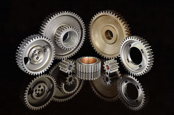
Some Custom CHINAMFG & Moulds for Your Reference.
Neway Highly Welcome Your Own Custom Designs !!!
Neway Support Custom Design Moulds & Moulds Export.
Neway Can Also Provide Mould Spare Parts Export, eg: Slider, Inserts, Ejector Pins, etc.
NEWAY has complete production chain from R&D, Rapid Prototypes, mould design, mould making, components production, assembling, packing to export. Having 1 supplier like CHINAMFG for the complete assembly will allow for better design, quality, and fit of all the individual parts.
The most common used surface treatment are: Matte, Texture (fine texture, rough texture…), Common Polishing, Mirror Polishing, Laser Engraving, Printing, Plating, Brushing, Marbling), etc. You can view below surface pictures for reference
Company Profile
Our Advantages
Good reviews of customer
Certifications
Below are some inspection equipment for reference:
And attach the injection molding CHINAMFG inspection report for reference:
Packaging & Shipping
FAQ
Q1. How soon can I get a precise quotation for custom plastic injection part?
A1: Please send us your inquiry by email or Alibaba TM message. Once we confirm the design (Feature details with parameters), material, color, qty, we can provide quotation within 24 HOURS.
Q2: Can I get a free sample, how long will it take?
A2: a. For standard products we have in stock, YES for free sample, but the express fee will be charged in advance.
Mostly, it takes 3-10 days.
b. For custom products, sample fee is determined by the detailed sample requirements. Normally, it takes 7-15 days.
Q3: Can you make custom parts based on my sample?
A3: Yes, you can send the sample to us by express and we will evaluate the sample, scan the features and draft 3D drawing for production.
Q4: What does your OEM service include?
A4: We follow up your request from the design idea to the mass production.
a. You can provide 3D drawing to us, then our engineers and production teams evaluate the design and quote you the precise cost.
b. If you don’t have 3D drawing, you can provide 2D drawing or draft with features details with full dimensions, we can draft 3D drawing for you with fair charge.
c. You can also customize Logo on the product surface, package, color box or carton.
d. We also provide assembly service for the OEM parts.
Q5. What is your payment term?
A5: We accept T/T, Paypal, Western Union, L/C, Alibaba Trade Assurance.
Work with Neway, your business is in safe and your money is in safe!
If you can dream it, we can build it!
| Application: | Motor, Electric Cars, Motorcycle, Machinery, Car, Others |
|---|---|
| Hardness: | Hardened Tooth Surface |
| Gear Position: | Internal Gear |
| Manufacturing Method: | Plastic Injection |
| Toothed Portion Shape: | Bevel Wheel |
| Material: | Plastic |
| Samples: |
US$ 10/Piece
1 Piece(Min.Order) | |
|---|
| Customization: |
Available
| Customized Request |
|---|

How do you address noise and vibration issues in a spur gear system?
Noise and vibration issues in a spur gear system can significantly impact its performance, efficiency, and overall user experience. Here’s a detailed explanation of how to address noise and vibration issues in a spur gear system:
- Gear Design: Optimize the gear design to minimize noise and vibration. Consider factors such as tooth profile, gear module or pitch, and the number of teeth to ensure smooth and quiet gear operation. Proper gear design helps reduce gear meshing impacts and tooth-to-tooth variations, which are common sources of noise and vibration.
- Accurate Gear Alignment: Ensure precise gear alignment to minimize misalignment-induced noise and vibration. Misalignment between the gears can cause uneven loading, increased backlash, and gear meshing irregularities, leading to noise and vibration. Proper alignment techniques, such as using alignment tools or measuring devices, should be employed during gear installation and maintenance.
- Surface Finish and Tooth Quality: Ensure proper surface finish and high-quality tooth profiles on the gears. Rough surfaces or manufacturing defects can contribute to noise and vibration. Gears with accurate tooth profiles and smooth finishes experience better meshing and reduced friction, resulting in lower noise and vibration levels.
- Lubrication: Proper lubrication is crucial for reducing friction, wear, and noise generation in spur gear systems. Use the recommended lubricant type and ensure sufficient lubricant film thickness between gear teeth. Regular lubricant analysis and replacement are important to maintain optimal lubrication performance and minimize noise and vibration issues.
- Load Distribution: Evaluate the load distribution within the gear system to minimize localized loading and potential noise sources. Proper gear design, tooth profile optimization, and gear arrangement can help distribute the load evenly, reducing noise and vibration caused by uneven loading conditions.
- Resonance Analysis and Damping: Conduct resonance analysis to identify and address potential resonant frequencies within the gear system. Resonance can amplify noise and vibration. Techniques such as adding damping materials, using vibration isolators, or adjusting gear configurations can help mitigate resonance-related noise and vibration issues.
- Noise and Vibration Testing: Perform noise and vibration testing during the development and maintenance stages of the gear system. This involves using specialized equipment to measure and analyze noise and vibration levels. Testing helps identify specific sources of noise and vibration, allowing for targeted solutions and improvements.
- Isolation and Absorption: Implement isolation and absorption techniques to minimize noise and vibration transmission to surrounding structures or components. This can include using vibration isolators, resilient mounts, or incorporating vibration-absorbing materials to reduce the propagation of noise and vibration beyond the gear system.
- Regular Maintenance and Inspection: Implement a proactive maintenance program to monitor gear performance and identify potential noise and vibration issues. Regular inspections, including gear tooth wear analysis, lubricant checks, and alignment verification, allow for early detection and rectification of any problems that may contribute to noise and vibration.
By considering these approaches and implementing appropriate measures, it is possible to address noise and vibration issues in a spur gear system, resulting in quieter and smoother gear operation.
It’s important to note that the specific techniques and solutions for addressing noise and vibration may vary depending on the gear system’s application, design, and operating conditions. Consulting with gear manufacturers, industry experts, or vibration specialists can provide further guidance in addressing noise and vibration issues specific to a spur gear system.
Can you provide examples of machinery that use spur gears?
Spur gears are widely used in various machinery and mechanical systems due to their simplicity, efficiency, and versatility. Here are some examples of machinery and equipment that commonly utilize spur gears:
- Automotive Industry: Spur gears are found in various automotive applications, including manual transmissions, differential gears, and starter motors. They are used to transmit power and torque efficiently in these systems.
- Mechanical Clocks and Watches: Traditional mechanical clocks and watches often utilize spur gears to transfer rotational motion from the mainspring to the hour, minute, and second hands. These gears play a crucial role in accurate timekeeping.
- Printing Presses: Spur gears are employed in printing presses to synchronize the movement of different components, such as rollers and paper feed mechanisms. They ensure precise and coordinated operation during the printing process.
- Industrial Machinery: Many types of industrial machinery rely on spur gears, including conveyors, packaging equipment, textile machinery, and machine tools. Spur gears help transmit power and control the movement of various components in these machines.
- Power Plants: Spur gears can be found in power generation facilities, such as steam turbines and gas turbines. They help transfer rotational motion from the turbine shaft to the generator shaft, enabling the production of electrical power.
- Agricultural Equipment: Agricultural machinery, such as tractors, combines, and harvesters, often utilize spur gears in their drive systems. These gears help transmit power from the engine to the wheels or other operational components.
- Robotics and Automation Systems: Spur gears are commonly used in robotics and automation systems to transmit power and control the movement of robotic arms, conveyor systems, and other mechanical components.
- Power Tools: Many power tools, including drills, saws, and grinders, incorporate spur gears in their gearboxes. These gears help increase torque and provide the necessary speed reduction for efficient tool operation.
These examples represent just a few of the many applications where spur gears are utilized. Spur gears’ simplicity, cost-effectiveness, and ability to handle high load capacities make them suitable for a wide range of machinery and mechanical systems in various industries.
It’s important to note that different gear types, such as helical gears, bevel gears, or planetary gears, may also be used in conjunction with spur gears or in different applications depending on specific requirements and design considerations.
How do you choose the right size spur gear for your application?
Choosing the right size spur gear for your application requires careful consideration of various factors. Here’s a detailed explanation of the steps involved in selecting the appropriate size spur gear:
- Determine the Required Torque: Start by determining the torque requirements of your application. Calculate or estimate the maximum torque that the gear will need to transmit. Consider factors such as the power input, speed, and load conditions to determine the required torque.
- Identify the Speed Requirements: Determine the desired rotational speed or RPM (revolutions per minute) for your application. This will help in selecting a gear with the appropriate pitch diameter and tooth configuration to achieve the desired speed.
- Consider the Load Conditions: Evaluate the expected load conditions, including the magnitude and direction of the load. Determine if the load is constant or variable, and if it involves shock loads or cyclic loading. This will impact the gear’s durability and load-carrying capacity.
- Calculate the Pitch Diameter: Based on the torque and speed requirements, calculate the pitch diameter of the spur gear. The pitch diameter is determined by the formula: Pitch Diameter = (2 x Torque) / (Pressure Angle x Allowable Tooth Shear Stress).
- Select the Module Size: Choose an appropriate module size based on the gear size and application requirements. The module size determines the tooth size and spacing. Smaller module sizes are used for fine tooth profiles and higher precision, while larger module sizes are suitable for heavier loads and higher torque applications.
- Determine the Number of Teeth: Based on the pitch diameter and module size, calculate the number of teeth required for the gear. Ensure that the gear has an adequate number of teeth for smooth operation, load distribution, and sufficient contact ratio.
- Consider Space Constraints: Evaluate the available space and mounting requirements in your application. Ensure that the selected gear size can fit within the available space and can be properly mounted on the shaft or gearbox.
- Choose the Material: Consider the operating conditions, such as temperature, humidity, and presence of corrosive substances, to select the appropriate material for the spur gear. Common materials include steel, cast iron, brass, and plastic. Choose a material that offers the necessary strength, wear resistance, and durability for your specific application.
- Consider Additional Design Features: Depending on your application requirements, you may need to consider additional design features such as profile shift, hub configuration, and surface treatments. Profile shift can optimize gear performance, while specific hub configurations and surface treatments may be necessary for proper mounting and enhanced durability.
It’s important to note that gear selection is a complex process, and it may require consultation with gear manufacturers or experts in the field. They can provide guidance based on their expertise and assist in selecting the most suitable spur gear for your specific application.
By thoroughly considering factors such as torque requirements, speed, load conditions, pitch diameter, module size, number of teeth, space constraints, material selection, and additional design features, you can choose the right size spur gear that meets the demands of your application in terms of performance, durability, and efficiency.


editor by CX 2023-09-12